Recently, Zach Feldman of NY Code and Design Academy, kindly lent me an Ubuntu-running Chromebook. With this, I continue on my project from the perspective of a Linux user instead of Windows. Moreover, I've discontinued use of the Sensor Tag, and instead have switched to using the Spark Core and again, the Adafruit sensors (accelerometer and gyroscope). This change seems beneficial as I found it personally difficult to use the Sensor Tag and use its libraries, whereas the Spark Core uses Arduino-based coding which I am more familiar with (as I haven't learned enough Android App development yet for the Sensor Tag).
For starters, my first goal was to connect my core to my Spark account and to the WiFi. You can find all the helpful instructions for this at the Spark Documentation: Connecting your Core. Seemed simple enough, but instantly I already found my first problem. Strangely, it seemed to be unable to find the spark core and connect it with my Android phone (Galaxy S3). However, Spark planned for that occurrence, and provides instructions to connect to the core manually. And so, following the Spark Documentation, I tried connecting to the core manually using the command line terminal. To be frank, it was somewhat difficult following the instructions for this because it is my first time working with Ubuntu.
If you are trying to connect your core manually, you'll be linked to the Github page for this. If you are using Ubuntu, DO NOT install node.js. If you read further, it provides another link to separate instructions on what to type into the terminal. However, when I typed "$ spark" and then "$ spark setup", I still kept getting the error that read something like "is your core connected? Make sure it's blinking blue". It was blinking blue, I swear! However, what I learned from my mentor, Sara Chipps, was that every time you plug in your core specifically to an Ubuntu computer, you have to first type in "$ sudo chmod 666 /dev/ttyACM0" before you type "$ spark setup". Why? I'm not sure, but it works! haha.
After you type in "$ spark set up", you should type in your log in information you may have created earlier on the build sign up. Then you will be asked to assign a WiFi network to the core and also name it as you please. Then you can log in on build.spark.io/build and your core should already automatically be recognized by your account. From here, you can start programming!
Showing posts with label programming. Show all posts
Showing posts with label programming. Show all posts
Wednesday, April 15, 2015

Sunday, July 20, 2014
Wiring and Arduino Code
I was able to successfully program the gyroscope and accelerometer to work together on the Arduino!!
It was difficult wiring them together as both sensors require the GND and 5V pins on the Arduino. However, thanks to my friend, I learned that I can use the breadboard to help wire them in a series.
Basically, it's where you use one end of the jumper wire to connect to the GND pin on the Arduino Uno for example. Then you'd connect the other end to the GND pin on the accelerometer. Then using a space on the breadboard in the same row as the GND pin of the accelerometer, place the end of a second jumper wire. The other end of that second jumper wire will go into the GND pin of the gyroscope. It'd be best to place the end of the second jumper wire in a space directly next to the one of the accelerometer. However, if it's any space of that row, it should technically work the same.

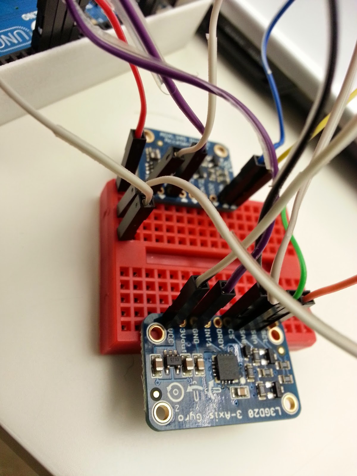 In the photo to the right, you can see how I connected the wires in a row.
The photo to the left shows just the general view of all the wires I used to connect the pins.
I didn't solder anything. Was going to save that until the end.
So yea, that was one cool and usefull trick I learned!
Anyways, here's the code I used:
It was difficult wiring them together as both sensors require the GND and 5V pins on the Arduino. However, thanks to my friend, I learned that I can use the breadboard to help wire them in a series.
Basically, it's where you use one end of the jumper wire to connect to the GND pin on the Arduino Uno for example. Then you'd connect the other end to the GND pin on the accelerometer. Then using a space on the breadboard in the same row as the GND pin of the accelerometer, place the end of a second jumper wire. The other end of that second jumper wire will go into the GND pin of the gyroscope. It'd be best to place the end of the second jumper wire in a space directly next to the one of the accelerometer. However, if it's any space of that row, it should technically work the same.
In the photo to the right, you can see how I connected the wires in a row.The photo to the left shows just the general view of all the wires I used to connect the pins.
I didn't solder anything. Was going to save that until the end.
So yea, that was one cool and usefull trick I learned!
Anyways, here's the code I used:
#include#include #include #include #include // Define the pins for SPI #define GYRO_CS 4 // labeled CS #define GYRO_DO 5 // labeled SA0 #define GYRO_DI 6 // labeled SDA #define GYRO_CLK 7 // labeled SCL Adafruit_L3GD20 gyro(GYRO_CS, GYRO_DO, GYRO_DI, GYRO_CLK); /* Assign a unique ID to this sensor at the same time */ Adafruit_ADXL345_Unified accel = Adafruit_ADXL345_Unified(12345); //Declaring timer SimpleTimer timer; void displaySensorDetails(void) { sensor_t sensor; accel.getSensor(&sensor); Serial.println("------------------------------------"); Serial.print ("Sensor: "); Serial.println(sensor.name); Serial.print ("Driver Ver: "); Serial.println(sensor.version); Serial.print ("Unique ID: "); Serial.println(sensor.sensor_id); Serial.print ("Max Value: "); Serial.print(sensor.max_value); Serial.println(" m/s^2"); Serial.print ("Min Value: "); Serial.print(sensor.min_value); Serial.println(" m/s^2"); Serial.print ("Resolution: "); Serial.print(sensor.resolution); Serial.println(" m/s^2"); Serial.println("------------------------------------"); Serial.println(""); delay(500); } void displayDataRate(void) { Serial.print ("Data Rate: "); switch(accel.getDataRate()) { case ADXL345_DATARATE_3200_HZ: Serial.print ("3200 "); break; case ADXL345_DATARATE_1600_HZ: Serial.print ("1600 "); break; case ADXL345_DATARATE_800_HZ: Serial.print ("800 "); break; case ADXL345_DATARATE_400_HZ: Serial.print ("400 "); break; case ADXL345_DATARATE_200_HZ: Serial.print ("200 "); break; case ADXL345_DATARATE_100_HZ: Serial.print ("100 "); break; case ADXL345_DATARATE_50_HZ: Serial.print ("50 "); break; case ADXL345_DATARATE_25_HZ: Serial.print ("25 "); break; case ADXL345_DATARATE_12_5_HZ: Serial.print ("12.5 "); break; case ADXL345_DATARATE_6_25HZ: Serial.print ("6.25 "); break; case ADXL345_DATARATE_3_13_HZ: Serial.print ("3.13 "); break; case ADXL345_DATARATE_1_56_HZ: Serial.print ("1.56 "); break; case ADXL345_DATARATE_0_78_HZ: Serial.print ("0.78 "); break; case ADXL345_DATARATE_0_39_HZ: Serial.print ("0.39 "); break; case ADXL345_DATARATE_0_20_HZ: Serial.print ("0.20 "); break; case ADXL345_DATARATE_0_10_HZ: Serial.print ("0.10 "); break; default: Serial.print ("???? "); break; } Serial.println(" Hz"); } void displayRange(void) { Serial.print ("Range: +/- "); switch(accel.getRange()) { case ADXL345_RANGE_16_G: Serial.print ("16 "); break; case ADXL345_RANGE_8_G: Serial.print ("8 "); break; case ADXL345_RANGE_4_G: Serial.print ("4 "); break; case ADXL345_RANGE_2_G: Serial.print ("2 "); break; default: Serial.print ("?? "); break; } Serial.println(" g"); } int led = 13; //int times = 0; //int last_Value =0; void setup() { Serial.begin(9600); // Try to initialise and warn if we couldn't detect the chip while (!gyro.begin(gyro.L3DS20_RANGE_250DPS)) { Serial.println("Oops ... unable to initialize the L3GD20. Check your wiring!"); // while (1); } Serial.begin(9600); Serial.println("Accelerometer Test"); Serial.println(""); pinMode(led, OUTPUT); /* Initialise the sensor */ while(!accel.begin()) { /* There was a problem detecting the ADXL345 ... check your connections */ Serial.println("Ooops, no ADXL345 detected ... Check your wiring!"); } /* Set the range to whatever is appropriate for your project */ accel.setRange(ADXL345_RANGE_4_G); // displaySetRange(ADXL345_RANGE_8_G); // displaySetRange(ADXL345_RANGE_16_G); // displaySetRange(ADXL345_RANGE_2_G); /* Display some basic information on this sensor */ displaySensorDetails(); /* Display additional settings (outside the scope of sensor_t) */ displayDataRate(); displayRange(); Serial.println(""); timer.setInterval(1000, breath); timer.setInterval(20000, breathChk); } void loop() { gyro.read(); Serial.print("gX: "); Serial.print((int)gyro.data.x); Serial.print(" "); Serial.print("gY: "); Serial.print((int)gyro.data.y); Serial.print(" "); Serial.print("gZ: "); Serial.println((int)gyro.data.z); Serial.print(" "); delay(100); //int new_value = 0; //times = times + 1; //Serial.print(times); /* Get a new sensor event */ sensors_event_t event; accel.getEvent(&event); /* Display the results (acceleration is measured in m/s^2) */ Serial.print("aX: "); Serial.print(event.acceleration.x); Serial.print(" "); Serial.print("aY: "); Serial.print(event.acceleration.y); Serial.print(" "); Serial.print("aZ: "); Serial.print(event.acceleration.z); Serial.print(" ");Serial.println("m/s^2 "); delay(500); timer.run(); // last_value != new_value // MOVEMENT // last_value = new_value }
BY THE WAY.
I have stopped using Arduino as the basis of my Intel project. Instead, I will be using Texas Instrument's Sensor Tag product.
Subscribe to:
Posts (Atom)