Recently, Zach Feldman of NY Code and Design Academy, kindly lent me an Ubuntu-running Chromebook. With this, I continue on my project from the perspective of a Linux user instead of Windows. Moreover, I've discontinued use of the Sensor Tag, and instead have switched to using the Spark Core and again, the Adafruit sensors (accelerometer and gyroscope). This change seems beneficial as I found it personally difficult to use the Sensor Tag and use its libraries, whereas the Spark Core uses Arduino-based coding which I am more familiar with (as I haven't learned enough Android App development yet for the Sensor Tag).
For starters, my first goal was to connect my core to my Spark account and to the WiFi. You can find all the helpful instructions for this at the Spark Documentation: Connecting your Core. Seemed simple enough, but instantly I already found my first problem. Strangely, it seemed to be unable to find the spark core and connect it with my Android phone (Galaxy S3). However, Spark planned for that occurrence, and provides instructions to connect to the core manually. And so, following the Spark Documentation, I tried connecting to the core manually using the command line terminal. To be frank, it was somewhat difficult following the instructions for this because it is my first time working with Ubuntu.
If you are trying to connect your core manually, you'll be linked to the Github page for this. If you are using Ubuntu, DO NOT install node.js. If you read further, it provides another link to separate instructions on what to type into the terminal. However, when I typed "$ spark" and then "$ spark setup", I still kept getting the error that read something like "is your core connected? Make sure it's blinking blue". It was blinking blue, I swear! However, what I learned from my mentor, Sara Chipps, was that every time you plug in your core specifically to an Ubuntu computer, you have to first type in "$ sudo chmod 666 /dev/ttyACM0" before you type "$ spark setup". Why? I'm not sure, but it works! haha.
After you type in "$ spark set up", you should type in your log in information you may have created earlier on the build sign up. Then you will be asked to assign a WiFi network to the core and also name it as you please. Then you can log in on build.spark.io/build and your core should already automatically be recognized by your account. From here, you can start programming!
Wednesday, April 15, 2015
Thursday, July 24, 2014
Unrooting the Galaxy S3!
I have two phones. One for personal use and one for my project; both Samsung Galaxy S3. My personal phone is updated to version 4.4.2. My project pone was at version 4.1.
This let me know that my 4.1 phone could be updated to 4.4.2, which is needed since the Sensor Tag only works with Android versions 4.3 or later.
However, I forgot to update my project phone. And so, when rooting my project phone (which I posted about earlier), I flashed a ROM for 4.4.2 instead of 4.1. This was not good as rooting needs ROMs that are meant for your specific version type. A warning for rooting phones is that you might not be able to get firmware updates. Thus, I wasn't able to update the version of phone, which was needed since Sensor Tag can only work with versions 4.3 and higher on Android.
So here is a How to Unroot the Galaxy S3 Guide! :)
Guide link
^this guide is really easy to follow, so I'll just direct you over to it. Lots of pictures!!
It also provides the complete stock file for the Samsung Galaxy S3, so no need to go searching for it! Yay :-)
However, unlike the previous How-To I wrote for rooting a phone, this How-To uses Heimdall instead of Odin. I couldn't really find any guide easy to follow for unrooting with Odin (if you know one, please feel free to share!).
I unrooted my phone in order to unbrick it, updated the version, and then re-followed the instructions to root it again. Now, my phone is rooted and working properly!
Wednesday, July 23, 2014
Switching Over to the Sensor Tag!
Hi!
For this project, I've been using Arduino and Adafruit sensor products. However, recently, I've found out about Texas Instruments's product the Sensor Tag.
The Sensor Tag is basically a compact device that carries six small sensors that is Bluetooth smart. It is meant to be programmed for phone applications and is just generally really awesome!!
And so, from now on I will be posting things related to how I am using the Sensor Tag product! :-)
Just wanted to explain the sudden shift.
Haha, now I just have an Arduino and two Adafruit sensors being neglected in my drawer... It was really fun to program with Arduino and exciting to get the sensors to work together though!
Rooting Samsung Galaxy S3
Since my project involves making a phone application, I've begun preparing it for development!
It is a Sprint Samsung Galaxy S3 Android 4.4.2 kitkat smartphone. Benefit of having an Android phone for this is that I can root it.
To be honest, I googled around for information on rooting, and recently learned it within a day or so. It wasn't all that hard in my opinion. And hey, if a simple ol' teenage girl can do it, then so can you! :-)
Disclaimer: I'm a total noobie, and learned this from Google.
What is rooting?
Well, I thought of "tree" when I first heard of this. However, it's far from that.
Rooting is getting command access within the Android phone's system. This control is known as "root access" or "root permissions". I think of it as something similar to getting administrative access on a computer. You're able to have full control of what can be allowed and disallowed on the phone. There's no security wall to stop you, and so this allows you to have a smooth developing environment for phone enhancements and applications.
Common Warnings:
- Risking warranty of phone plan
- Damaging your smartphone (making it freeze or unable to use it again)
- Risk of not receiving firmware updates.
How to Root Galaxy S3?
Rooting is tricky as you do need a specific ROM for the specific phone type and version you have. Thus, my instructions is for the Galaxy S3 on 4.4.2 kitkat. (Note: Thus, if you have version 4.1 or something, you could mess up your phone).
(Main points of instructions rephrased from this guide. Pictures are mine, except for one in step 5)
- Download Odin and CF-Auto-Root zip files and extra the files.
- Turn off your phone completely.
 |
| That's my finger :-) |
- Turn your phone back on in Download Mode
- Press and hold Volume Down + Home Button + Power Button at the same time.
- Note: Hold all the buttons until after the vibration occurs. Don't let go when it vibrates or else it'll boot up normally.


- Launch the Odin .exe file and connect phone to computer. Wait for Odin to detect your phone.
- ID:COM box should be highlighted with color after phone is detected. Click PDA button and select the CF-Auto-Root tar file. Have only "Auto Reboot" and "F.Reset Time" boxes checked.
 |
| Odin |
- Click start
- Let device reboot automatically
- Mine needed me to reboot manually as Odin said it was successful but wouldn't auto reboot.
If you turn off your phone and turn it back on in download mode, you can see that it's rooted by looking at what it says in the top left corner. It should specifically say the following:
Current Binary: Custom
System Status: Custom
and I think Warranty Bit should be any number except for 0.
 |
| Top left text when in download mode |
You can also download the free app SU Root Checker to check if your device is rooted or not, which may be easier in some ways.
 |
| Screenshot of Root Checker app from phone |
Another app you can get is the SuperSU app from ChainFire if it doesn't come on your phone automatically.
Other Helpful links:
Other Helpful links:
Sunday, July 20, 2014
Wiring and Arduino Code
I was able to successfully program the gyroscope and accelerometer to work together on the Arduino!!
It was difficult wiring them together as both sensors require the GND and 5V pins on the Arduino. However, thanks to my friend, I learned that I can use the breadboard to help wire them in a series.
Basically, it's where you use one end of the jumper wire to connect to the GND pin on the Arduino Uno for example. Then you'd connect the other end to the GND pin on the accelerometer. Then using a space on the breadboard in the same row as the GND pin of the accelerometer, place the end of a second jumper wire. The other end of that second jumper wire will go into the GND pin of the gyroscope. It'd be best to place the end of the second jumper wire in a space directly next to the one of the accelerometer. However, if it's any space of that row, it should technically work the same.

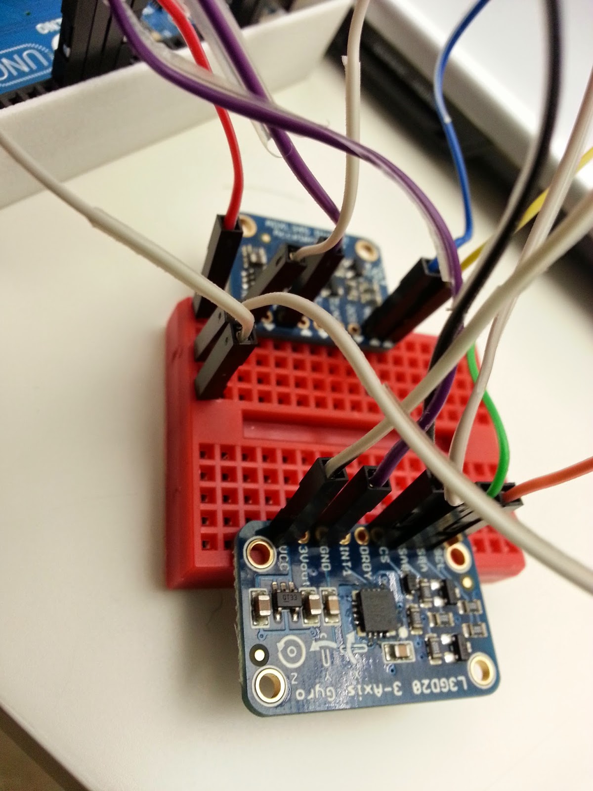 In the photo to the right, you can see how I connected the wires in a row.
The photo to the left shows just the general view of all the wires I used to connect the pins.
I didn't solder anything. Was going to save that until the end.
So yea, that was one cool and usefull trick I learned!
Anyways, here's the code I used:
It was difficult wiring them together as both sensors require the GND and 5V pins on the Arduino. However, thanks to my friend, I learned that I can use the breadboard to help wire them in a series.
Basically, it's where you use one end of the jumper wire to connect to the GND pin on the Arduino Uno for example. Then you'd connect the other end to the GND pin on the accelerometer. Then using a space on the breadboard in the same row as the GND pin of the accelerometer, place the end of a second jumper wire. The other end of that second jumper wire will go into the GND pin of the gyroscope. It'd be best to place the end of the second jumper wire in a space directly next to the one of the accelerometer. However, if it's any space of that row, it should technically work the same.
In the photo to the right, you can see how I connected the wires in a row.The photo to the left shows just the general view of all the wires I used to connect the pins.
I didn't solder anything. Was going to save that until the end.
So yea, that was one cool and usefull trick I learned!
Anyways, here's the code I used:
#include#include #include #include #include // Define the pins for SPI #define GYRO_CS 4 // labeled CS #define GYRO_DO 5 // labeled SA0 #define GYRO_DI 6 // labeled SDA #define GYRO_CLK 7 // labeled SCL Adafruit_L3GD20 gyro(GYRO_CS, GYRO_DO, GYRO_DI, GYRO_CLK); /* Assign a unique ID to this sensor at the same time */ Adafruit_ADXL345_Unified accel = Adafruit_ADXL345_Unified(12345); //Declaring timer SimpleTimer timer; void displaySensorDetails(void) { sensor_t sensor; accel.getSensor(&sensor); Serial.println("------------------------------------"); Serial.print ("Sensor: "); Serial.println(sensor.name); Serial.print ("Driver Ver: "); Serial.println(sensor.version); Serial.print ("Unique ID: "); Serial.println(sensor.sensor_id); Serial.print ("Max Value: "); Serial.print(sensor.max_value); Serial.println(" m/s^2"); Serial.print ("Min Value: "); Serial.print(sensor.min_value); Serial.println(" m/s^2"); Serial.print ("Resolution: "); Serial.print(sensor.resolution); Serial.println(" m/s^2"); Serial.println("------------------------------------"); Serial.println(""); delay(500); } void displayDataRate(void) { Serial.print ("Data Rate: "); switch(accel.getDataRate()) { case ADXL345_DATARATE_3200_HZ: Serial.print ("3200 "); break; case ADXL345_DATARATE_1600_HZ: Serial.print ("1600 "); break; case ADXL345_DATARATE_800_HZ: Serial.print ("800 "); break; case ADXL345_DATARATE_400_HZ: Serial.print ("400 "); break; case ADXL345_DATARATE_200_HZ: Serial.print ("200 "); break; case ADXL345_DATARATE_100_HZ: Serial.print ("100 "); break; case ADXL345_DATARATE_50_HZ: Serial.print ("50 "); break; case ADXL345_DATARATE_25_HZ: Serial.print ("25 "); break; case ADXL345_DATARATE_12_5_HZ: Serial.print ("12.5 "); break; case ADXL345_DATARATE_6_25HZ: Serial.print ("6.25 "); break; case ADXL345_DATARATE_3_13_HZ: Serial.print ("3.13 "); break; case ADXL345_DATARATE_1_56_HZ: Serial.print ("1.56 "); break; case ADXL345_DATARATE_0_78_HZ: Serial.print ("0.78 "); break; case ADXL345_DATARATE_0_39_HZ: Serial.print ("0.39 "); break; case ADXL345_DATARATE_0_20_HZ: Serial.print ("0.20 "); break; case ADXL345_DATARATE_0_10_HZ: Serial.print ("0.10 "); break; default: Serial.print ("???? "); break; } Serial.println(" Hz"); } void displayRange(void) { Serial.print ("Range: +/- "); switch(accel.getRange()) { case ADXL345_RANGE_16_G: Serial.print ("16 "); break; case ADXL345_RANGE_8_G: Serial.print ("8 "); break; case ADXL345_RANGE_4_G: Serial.print ("4 "); break; case ADXL345_RANGE_2_G: Serial.print ("2 "); break; default: Serial.print ("?? "); break; } Serial.println(" g"); } int led = 13; //int times = 0; //int last_Value =0; void setup() { Serial.begin(9600); // Try to initialise and warn if we couldn't detect the chip while (!gyro.begin(gyro.L3DS20_RANGE_250DPS)) { Serial.println("Oops ... unable to initialize the L3GD20. Check your wiring!"); // while (1); } Serial.begin(9600); Serial.println("Accelerometer Test"); Serial.println(""); pinMode(led, OUTPUT); /* Initialise the sensor */ while(!accel.begin()) { /* There was a problem detecting the ADXL345 ... check your connections */ Serial.println("Ooops, no ADXL345 detected ... Check your wiring!"); } /* Set the range to whatever is appropriate for your project */ accel.setRange(ADXL345_RANGE_4_G); // displaySetRange(ADXL345_RANGE_8_G); // displaySetRange(ADXL345_RANGE_16_G); // displaySetRange(ADXL345_RANGE_2_G); /* Display some basic information on this sensor */ displaySensorDetails(); /* Display additional settings (outside the scope of sensor_t) */ displayDataRate(); displayRange(); Serial.println(""); timer.setInterval(1000, breath); timer.setInterval(20000, breathChk); } void loop() { gyro.read(); Serial.print("gX: "); Serial.print((int)gyro.data.x); Serial.print(" "); Serial.print("gY: "); Serial.print((int)gyro.data.y); Serial.print(" "); Serial.print("gZ: "); Serial.println((int)gyro.data.z); Serial.print(" "); delay(100); //int new_value = 0; //times = times + 1; //Serial.print(times); /* Get a new sensor event */ sensors_event_t event; accel.getEvent(&event); /* Display the results (acceleration is measured in m/s^2) */ Serial.print("aX: "); Serial.print(event.acceleration.x); Serial.print(" "); Serial.print("aY: "); Serial.print(event.acceleration.y); Serial.print(" "); Serial.print("aZ: "); Serial.print(event.acceleration.z); Serial.print(" ");Serial.println("m/s^2 "); delay(500); timer.run(); // last_value != new_value // MOVEMENT // last_value = new_value }
BY THE WAY.
I have stopped using Arduino as the basis of my Intel project. Instead, I will be using Texas Instrument's Sensor Tag product.
Tuesday, February 25, 2014
A Bit of Details on My Project
As of right now, I'm waiting for my gyroscope to come in as it's part of the next step of my project. I have (for the most part) figured out how to work the accelerometer, and that's why I feel like I can move onto including a gyroscope as well (see previous post for more on my accelerometer progress).
However, as I'm waiting for the gyroscope to ship in, I've found a video that resembles the basic structure of how I want my project to turn out. It's a video called Arduino Multisensor, and it's of a bunch of sensors attached to an Arduino uno on a large breadboard.
The video shows a device similar to my idea as it has multiple sensors in one device that can change and output readings according to the different circumstances. However, differently, I'd like the readings of the data to show up on the user's mobile device and show all the readings at once instead of one at a time (but there may be an option setting for otherwise).
I probably won't use the barometer or compass, but most definitely the gyroscope, accelerometer, and thermometer with others to later be determined. Moreover, as the sensors in the video are spaced out onto a breadboard, I'd hope to make mine more compact as it'll be attached to a child.
This post's purpose is to give you more of an idea of what I'm trying to do, instead of an update of what I'm actually doing at the moment. As soon as my gyroscope comes in, I'll post more on updates!
Friday, February 21, 2014
More on Accelerometer!
I was able to figure out how to make the Arduino blink according to movement of the accelerometer!
From reading the helpful information on StackOverflow, I read that positive values indicate increased velocity and negative values indicate decreased velocity; while zero indicates constant velocity. With that said, I concluded that the positive and negative values will be when the baby breathes in and out. Whereas, on the other hand, zero would indicate that the baby has stopped breathing. And so, at the moment, I have the accelerometer have pin13 turn off when the values are not zero and turn on when it is zero. Later, I might make it more sensitive and have a warning for when the breathing of the baby slows.
In the last loop of the code I got from the guide, I added an if/else statement at the end. Also, outside the void setup placed earlier in the code, I had to write:
Code:
Planning on also ordering a gyroscope, which will help orientation reading. Another device to learn, haha.
Next step:
From reading the helpful information on StackOverflow, I read that positive values indicate increased velocity and negative values indicate decreased velocity; while zero indicates constant velocity. With that said, I concluded that the positive and negative values will be when the baby breathes in and out. Whereas, on the other hand, zero would indicate that the baby has stopped breathing. And so, at the moment, I have the accelerometer have pin13 turn off when the values are not zero and turn on when it is zero. Later, I might make it more sensitive and have a warning for when the breathing of the baby slows.
In the last loop of the code I got from the guide, I added an if/else statement at the end. Also, outside the void setup placed earlier in the code, I had to write:
int led = 13Inside the void setup, I wrote:
pinMode(led, OUTPUT).
Code:
void loop(void)
{
  /* Get a new sensor event */
  sensors_event_t event;
  accel.getEvent(&event);

  /* Display the results (acceleration is measured in m/s^2) */
  Serial.print("X: "); Serial.print(event.acceleration.x); Serial.print("  ");
  Serial.print("Y: "); Serial.print(event.acceleration.y); Serial.print("  ");
  Serial.print("Z: "); Serial.print(event.acceleration.z); Serial.print("  ");
  Serial.println("m/s^2 ");
  delay(500);
  if (event.acceleration.y != 0 && event.acceleration.z != 0)
    {
       digitalWrite(led,HIGH);

    }
  else if (event.acceleration.y == 0 && event.acceleration.z == 0)
    {
       digitalWrite(led, LOW);
    }
}Very simple, and it has worked for me. I didn't include "x" into the condition because I remember reading somewhere that x will always have same orientation and thus be of trouble in other calculations, or... something like that.
Planning on also ordering a gyroscope, which will help orientation reading. Another device to learn, haha.
Next step:
- How to work a gyroscope!
Subscribe to:
Posts (Atom)